How to prevent over pressurisation and avoid accidents when changing-over heat exchangers
How to prevent over-pressurisation of heat exchangers?
Heat exchangers heat up or cool down process fluids and gasses. They transfer heat between the process medium and a heating or cooling medium. They are widely applied in process plants, either to pre-heat or re-heat process fluids such as reboilers, or to pre-cool or re-condense them, such as condensers. They are commonly found around fractionating columns. Reboilers boil the liquid from the bottom of the column. Condensers condense the gases from the top of the column, before injecting them into the column again to increase the yield of the column. Heat exchangers are part of the core process, which runs non-stop between shut-down intervals.

Maintenance and hydrostatic testing
The continuous product flow contaminates the exchanger. Therefore, periodic maintenance is required. Testing of pressure vessels for transport and storage of gases is also very important, because such containers can explode if they fail under pressure. While heat exchangers must be maintained and tested in a live process, they are installed in parallel, allowing one to be maintained, while the other takes over the process. Changing over between heat exchangers requires strict adherence to procedures, to avoid hazardous mistakes.
Dangers associated with heat exchanger change-overs
When changing over between heat exchangers, the process should be able to keep flowing. If all exchangers are isolated at the same time, the flow is blocked, leading to instant explosion hazard.
- Overpressure by heating of residue. When heating medium flows, but the hydrocarbon flow is still blocked, residue in the heat exchanger vaporizes and rapidly expands.
- Equipment damage by frozen-up particles. When cooling medium flows, but the hydrocarbon flow is still blocked, residue in the heat exchanger freezes up, solidifies, and causes damage to the exchanger or other equipment
- Overpressure by blocked relief capacity. The path to the relief valve of the online heat exchanger must always be open. When blocked, overpressure builds up, causing rupture and explosion.
How to prevent over-pressurisation and avoid incidents?
- Never isolate all heat exchangers. One heat exchanger should be always online, so the process flow is never hindered.
- Always open outlets first. When starting up a heat exchanger, always open de outlet valves first so possible residue can exit.
- Always close inlets first. When shutting down a heat exchanger, always close the inlet valves first, so it does not get filled with fluids.
- Always have a PSV online. Ensure that the PSV is online when the heat exchanger is, so over pressure can always escape.


What are the common solutions for these scenarios currently?
To avoid dangers and incidents, such as loss of production time, or environmental damage, most companies have standard written operating procedures in place. In addition. most vessels are equipped with pressure and temperature transmitters to raise alarms. Written procedures and operating guidelines alone cannot ensure safe operations, as the human factor is not excluded. Alarms on the other hand do inform about sudden pressure and temperature increases, but this information is presented too late to act and prevent damage.
Avoid unsafe change-overs
Safety risks during changeovers can be minimised, by using valve interlocks. Valve interlocks guarantee operators follow the correct steps through a key transfer principle. Changeover operations take place in a safe sequence, without any short-cuts. The transfer of uniquely coded, linear keys from valve to valve, compel operators to follow the correct process steps. By interlocking the appropriate valves, you can prevent over-pressurisation, and ensure a layer of protection between the operator and the heat exchanger.
Using valve interlocks to guarantee safe change-over procedures
Valve interlocks are permanently mounted on each inlet and outlet valve. They must be unlocked to operate the valve. Keys are trapped in their lock. Only one is free at a time. With uniquely coded keys you can only operate the right valve at the right time. Valve changeover can be complex operational processes. If a process that requires operators to complete more than one step once, or reverse a process, additional sequence control products help operators to follow non-linear sequences, and ensure that an operation happens safely.
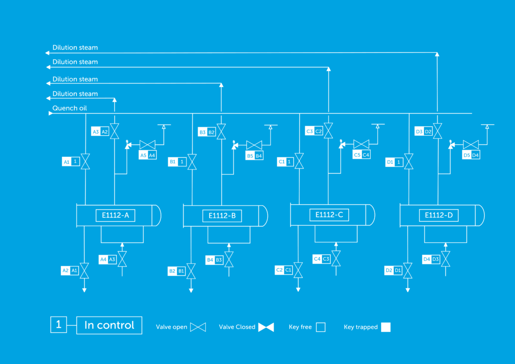
In below diagram, a heat exchanger changeover procedure is secured by means of an interlocked operation sequence.

Valve changeovers can be complex operational processes. If a process that requires operators to complete more than one step once, or reverse a process, additional sequence control products help operators to follow non-linear sequences, and ensure that an operation happens safely. Using valve interlocks to guarantee safe change-over procedures
In this diagram, a heat exchanger changeover procedure is secured by means of an interlocked operation sequence. In this process, four heat exchangers work in parallel. In case of maintenance, one of the heat exchangers should be isolated from the process. To guarantee safe valve operation, the valves are equipped with a valve interlock system.
Guaranteeing a safe manual valve operation sequence
When defining the right sequence of valve operation, the following rules need to be addressed:
- No product, steam or condensate flow during maintenance
- First isolate from the quench oil
- Then isolate from process water/dilution steam
- Keep the safety valve in process as long as possible
- Heat exchangers should switch to maintenance only one at a time
The inlet and outlet valves of the quench oil and process water/dilution steam, as well as the outlet valve of the safety valves, are equipped with interlocks. The valves are locked in open and closed position.
All the quench oil inlet valves of each heat exchanger are equipped with the same key code for the open position. By using only one start key, heat exchangers can be switched to maintenance mode only one at a time. All other key codes will be different to make sure that the valves will be operated in the right sequence. Please refer to the sequence drawing with the different key numbers that also represent a different key code.
The last valve that will be closed is the outlet of the safety valve. This guarantees that the heat exchanger is pressure protected until the end of the procedure. The end key of the sequence goes back to the control room, indicating the blocked heat exchanger. This information can be used to double check that the right equipment is isolated before starting maintenance.
This solution can be easily changed, expanded or simplified according to local requirements. Drain valves can be integrated into the sequence, based on the required level of safety and risk prevention. Pressure or temperature switches can also be integrated into the operating sequence, and valve status information can be communicated directly to the process control system.

