

How to avoid pitfalls and safety risks related to switchover processes of redundant PSV systems.
Guaranteeing over-pressure protection of pressure relief valves during switchover procedures
In process industry settings, ensuring the safe operation of pressure systems is paramount. Pressure relief valves (PRVs) are critical in preventing overpressure scenarios initiated by events like runaway reactions. They are the last safety barrier for protecting equipment and piping, supporting personal and environmental safety.
For the process industry, it is common practice to set up pressure relief systems in a redundant way to enable maintenance activities on the PRV´s during plant operation. Guaranteeing continuous overpressure protection, even during the switchover process, requires additional actions.
The best practice is to implement captive key lock systems, to ensure the operator follows the correct sequence of operational steps during this process.
Pressure Relief Valves (PRVs)
Pressure relief valves are safety devices designed to protect pressure vessels and systems from overpressure. They automatically release pressure when it exceeds a predetermined limit, thereby preventing potential equipment failure or catastrophic events.
Types of pressure relief valves
- Spring-loaded PRVs; a spring mechanism is used to open the valve at a set pressure.
- Pilot-operated PRVs; a pilot valve controls the main valve, offering more precise pressure control.
- Safety relief valves that combine features of both safety and relief valves, suitable for various applications.
Applications
PRVs are widely used in industries such as chemical processing, petrochemical, power generation, and oil and gas to ensure safe operation under varying pressure conditions.
How to avoid safety risks during switchover processes of redundant PRV valves?
Captive key locks
Captive key locks are mechanical devices designed to enforce a specific sequence of operations by requiring uniquely coded keys to be inserted or removed in a particular order. This ensures that certain actions cannot be performed out of sequence, thereby enhancing safety. Through customized adaptations, the captive key lock becomes an integral part of both upstream and downstream valves.
Benefits
- Prevents human error by ensuring that operations are performed in the correct order.
- Enhances safety by reducing the risk of accidents caused by incorrect operation sequences.
- Useful for many applications, in various industrial settings where safety is a priority.
Do you want to know how to guarantee over-pressure protection of your PRV valves?
Enhancing safety with captive key locks in PRV Systems
Integrating captive key locks on the inlet and outlet valves of a PSV (Pressure Safety Valve) system ensures the following:
- The standby PSV is brought into operation before the PSV intended for maintenance is taken out of service.
- The outlet valve cannot be closed until the inlet valve is closed.
These measures prevent potential hazards, such as overpressure in the protected system, which could result in equipment damage or safety incidents.
When using pilot-operated safety valves, it is essential to include the pilot line’s block valve in the sequence of operational steps. This ensures the correct setup pressure and guarantees the proper functioning of the PSV.
Activating the standby PSV before removing the primary PSV from service ensures seamless overpressure protection for the equipment.
Requiring the outlet valve to remain open until the inlet valve is closed prevents damage to the outlet side of the system. This is particularly important because the outlet pipeline is typically designed to handle lower pressure levels and has a larger cross-section. This design accounts for the increase in volume that occurs when the pressure of compressed gases is reduced.
Ensuring that the outlet valve can only be closed after the inlet valve has been closed guarantees that there will be no damage on the outlet side. This is important because the pipeline on the outlet side is usually designed for a lower pressure level with a larger cross-section. This is the consequence of the fact that when the pressure of compressed gases is reduced, the volume increases.
Valero Mereaux refinery explosion
An incident at a Hydrocracker unit in the U.S. state of Louisiana (CSB Incident Report Volume 1; January 14, 2025) serves as a striking example of how things can go wrong. In 2020, a mixture of hydrocarbon gases and hydrogen was accidentally released within the Hydrocracker unit. The flammable gas formed a cloud that ignited, resulting in an explosion and fire. One operator was seriously injured, and the incident caused approximately $5.15 million in property damage.
After a heavy rainstorm, the flow to the Hydrocracker unit’s flare began increasing. Valero operators found that although the unit’s cold separator was operating at normal working pressure, its emergency pressure-relief valve had malfunctioned and remained open, allowing flammable gas to flow into the flare system. Two managers at the refinery phoned the complex manager, who gave the onsite managers verbal approval to proceed with immediate actions to stop the flaring by reseating the safety device.
Valero uses the term ‘reseating’ when referring to trying to close and seal a malfunctioning emergency pressure-relief valve, by incrementally closing the inlet (upstream) isolation valve to lower the inlet pressure to the safety device. If the emergency pressure-relief device successfully closes (reseats), its inlet valve is reopened, which returns the safety device to its protective condition.
Valero’s onsite managers used the refinery’s management of change process for isolating a safety device, asking for Valero management approval for the operations team to perform the urgent reseating activity. One of the onsite managers, the operations supervisor, worked with two field operators to perform the reseating activity, while the board operator monitored the system pressure from the control room. Operations personnel raised safety concerns related to accessing either of the two 6-inch inlet valves, resulting in a decision to close the 20-inch outlet valve on the downstream side between the emergency pressure-relief valve and the flare system instead of trying to close one of the inlet valves.
The hazard of closing the outlet valve instead of closing one of the inlet valves was not recognized. Although the two 6-inch inlet valves were designed for high-pressure conditions (2,470 pounds per square inch (psi)), the 20-inch outlet valve to the flare system was rated for just 275 psi.
Closing the 20-inch outlet valve would expose it to approximately 2,100 psi of pressure from the flammable vapor flowing from the cold separator—far exceeding the valve’s pressure rating of 275 psi.
When the operations team had the outlet valve about 90 percent closed, the valve failed, releasing a high-pressure mixture of hydrogen and hydrocarbon vapor into the surrounding air. The flammable gas formed a vapor cloud, which ignited, resulting in the explosion and fire.
Valero reported that about 49,000 pounds of the hydrogen and hydrocarbon mixture were released.
Based on Valero’s investigation, the CSB determined that the probable cause of the accidental release, explosion, and fire was the closure of the 20-inch manual isolation outlet valve (located downstream of the emergency pressure-relief valve) instead of one of the two inlet (upstream) 6-inch isolation valves that were rated for the high-pressure condition.
How could this accident have been prevented?
Based on the probable cause, the implementation of a captive key lock system would have prevented the incident.
By adding captive key locks to the inlet and outlet valves including the right setup of the sequence of operational steps, the operator will be guided through the safe operation. The sequence needs to be set up in such a way, that the inlet valve will be closed before the outlet valve can be closed. This will be guaranteed by the use of uniquely coded keys.
The below sketch shows a redundant PSV system with inlet and outlet valves. PSV A is in process and PSV B is in standby mode, indicated by the closed inlet Valve V1 and open outlet valve V4. To take out PSV A for maintenance purposes, PSV B needs to be in process first. By using the start key 1 from the key cabinet in the control room, the inlet valve V1 can be unlocked and opened. After the valve is in open position, key 2 can be released and the valve is blocked in open position. Key one is trapped from the moment when valve 1 leaves the close position.
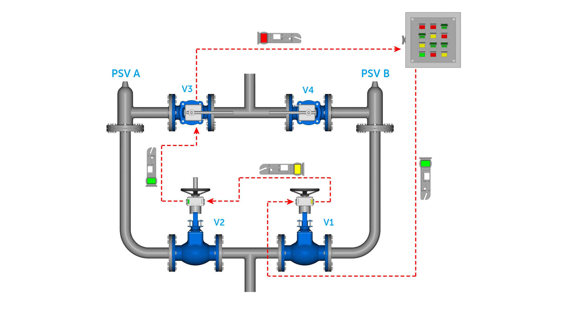
By inserting key 2 into the captive key lock of the inlet valve of PSV A, the valve can be operated and closed. By reaching the setup closed position, key 3 can be released and the valve is blocked. Because of the use of unique coded keys, key 3 will only fit into the captive key lock of the outlet valve of PSV A. After key 3 Is insert, the valve can be closed and key 4 released. When key 4 comes back to the control room, it indicates that PSV A is fully isolated and can be taken out for maintenance purposes.
This setup prevents the full isolation of the equipment from the pressure protection device, which is the last safety barrier as well as the fact that the outlet line and valve get over-pressured because of a still open inlet valve when there is a malfunction of the PSV
Installation guidelines
- Ensure PRVs and captive key locks are installed at strategic points in the system. The specification of the operation sequence needs to cover all the safety risks associated with the required operational steps.
- Select PRVs that are appropriately sized for the system’s pressure requirements.
Training
- Provide comprehensive training for operators on the correct use and maintenance of PRVs and captive key locks.
- Conduct safety drills to reinforce the importance of following the correct sequence of operations.