Interview with Stephan Sadowski (Head of Business Development) for Valve World, May 2021 edition, page 38-39.
Valve interlocks have evolved over the years, from mechanical, stand-alone devices to integrated electrical, electronical and mechanical solutions, according to Stephan Sadowski (Sofis). “The industry trend is towards increased control via central oversight and integration within the company’s process control systems.”
Mr. Sadowski has been working in the process safety sector for almost 25 years in various capacities. At the moment, he is the Head of Business Development at Sofis, a company that designs and produces systems for the safe and efficient operation of manual valves. These systems include valve interlocks, portable actuators, position indicators, key management systems and solutions for sequence control. The concise history of valve interlocks is that initially these devices were developed to safeguard process safety (and of course human and environmental safety) by separating process control from safety systems, hence the independent stand-alone approach towards mechanical valve interlocks. “Once a predefined sequence of operations has been established and safeguarded by interlocks, there is no other option available than to strictly follow that predefined sequence. As this sequence can never be altered or overridden, neither manually nor from the DCS, it ensures adherence to the safety procedures and thereby prevents human error”, Mr. Sadowski states.
Integrated approach
However, this approach to keep a strict separation between process control and safety systems has been slowly replaced by a more integrated vision, Mr. Sadowski says. “It is costly to maintain various structures for process control and safety systems. Therefore, many companies are considering a more integrated architecture. Besides system integration and subsequent cost reduction, other variables drive this phenomenon.
First, companies want more control over their operations, including safety systems. This means that all procedures are monitored in real-time at a central location, the control room. For example, which valves are open or closed, and who has used the valve interlock key at which point in time? Also, which operational or maintenance switchover sequences are currently ongoing?”
The second driver is related to the human factor. In some cases, the shortage and/or high turnaround in operating personnel increased the need for companies to tighten their grip on process control and safety systems.
Thirdly, the complexity of certain processes. “Pigging, for instance, is a notoriously complex process and associated with high risk if things go wrong. Therefore, a valve interlocking system enforcing predefined operational sequences minimizes this risk.”
Smart solutions
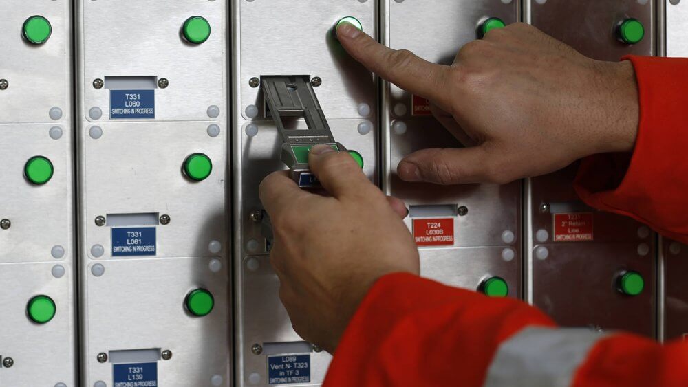
So what does the increased integration mean for the future of valve interlocks and interlock key cabinets? The answer is relatively simple: increased communication between in-field valve interlocks and control room systems leads to better monitoring of field operations and safety parameters. Mechanical interlocks can now be connected to the DCS and SIS through electro-mechanical and PLC-controlled key cabinets to create improved automation infrastructures. These cabinets allow for communicating detailed instructions (wireless, cable), monitoring the status of complex procedures, and operating part of a sequence from the control room. Moreover, process variables – for example, vessel pressure or H2S levels – can be incorporated within safeguarded operating procedures. In all, electro-mechanics enable mechanical valve interlocks to be fully integrated within the context of a common system for control and safety. Additional safeguards, such as electrical signals from the valve positioner via a switch box, can be incorporated into the system. By doing so, two different signals from different sources can be cross-checked to ensure the safe operation of valves. ‘Intelligent’ or ‘smart’ valve interlock products are based on the idea that ultimately all processes within a facility should somehow be interconnected to create substantial levels of overall process safety. If companies only focus on highly dangerous processes to be safeguarded and disregard the other less dangerous processes, they will never be able to guarantee SIL 3 and 4 safety levels, Mr. Sadowski says. Efficiency To conclude, ‘smart’ valve interlocks and key cabinets combine the reliable characteristics of mechanical valve interlocks with dynamic possibilities of electromechanical solutions. “By integrating operator procedures with DCS and SIS, it enables the integration of mechanical safety with electronic communication, authorization, and proofing possibilities. Integrating mechanical interlock systems within common infrastructures for plant control and plant safety also perfectly fits within the notion that ultimately all processes within a facility should be interconnected. This way, substantial improvements of process safety can be achieved, while at the same time realizing efficiency and cost savings.”
Case study Nord Stream
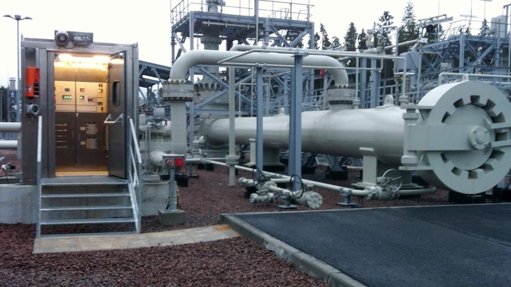
As part of the Nord Stream pipeline project, Sofis has designed and manufactured an electro-mechanical control cabinet in combination with a mechanical interlocking system for the pigging process. Pigging can – apart from its process complexity – also be dangerous if done incorrectly. In the case of Nord Stream, the pigging operations are even more complex as two end-users are involved and the control room is located in Switzerland, far away from the pig launching site in Russia and the pig receiving site in Germany. The custom-made, explosion-proof, and climate-controlled control cabinet, designed and manufactured in close cooperation with Siemens AG, displays the launcher and receiver layout, indicating vessel and pipeline pressure and valve positions at each stage of the sequence. The correct pressure readings and positions of valves are conditional requirements to release the keys enabling valve operation at each stage of the process. By locking the keys in place in a mechanical process control unit that forms part of the cabinet, only the correct process steps can be made and only when process parameters confirm that it is safe to do so. “This custom-designed solution combines the key cabinet, display, motor-operated valve (MOV) control system, and a mechanical trapped key interlock into one unit. Therefore, the pigging operation is as centrally located as possible, but still mechanically safeguarded by the interlocking system. The cabinet is connected to the client’s control system, allowing the central control room to monitor field operations at each step of the process.”

Custom-made, explosion-proof, and climate-controlled control cabinet, designed and manufactured in close co-operation with Siemens AG, displays the launcher and receiver layout, indicating vessel and pipeline pressure and valve positions at each stage of the sequence.
Case study storage
The added benefit of integrating valve interlock systems with DCS/PCS is demonstrated by a logistics provider in the Netherlands. The company, which stores powders and granulates, uses the system to allocate specific silos to specific orders/clients. When a tank truck checks in, the driver reports to the central control room after which his order details are entered into the company’s back-office system. When the order is accepted, the system selects a specific silo, and the corresponding valve interlock key is released to be handed over to the driver. Guided by LED-indicators and protected from any error by solenoids trapping the keys that are not authorized for release, the control room operator can only release the correct key from the cabinet. The control room operator hands the key to the driver to open the designated valve and silo. After loading, the driver returns the key to the control room to complete the order. During the process, the control room operator can track which valves and silos are in use, and which ones are idle.
This article has been published in the May 2021 edition of Valve World (page 38-39).


